A common misconception about 3D printing is that you can use the same CAD design for either plastic or metal. In reality, the processes are very different so design changes will be required. The type of modifications needed will depend on the type of metal 3D printing process being used. We will focus on powder bed fusion, which is what we use at Star Rapid.
3D CAD design software programs such as AUTOCAD, SolidWorks, NX and CATIA don’t distinguish between metal or plastic printing, so it’s up to the designer and the process engineer to exercise good judgement in changing both the design and the machine parameters for a successful build when converting from plastic to metal.

In our experience the three most important considerations that many designers don’t take into account when converting from plastic to metal 3D printing are the role of heat and associated thermal stress, the location of supports, and the importance of post-finishing.
CAD Design Differences Betweeen Plastic and Metal 3D Printing
Powerful lasers are used in metal powder bed fusion. These lasers generate localized hot spots, which are cooled by thermal conduction via the surrounding powder and the solidified lower layers.
Plastic does not conduct heat like metal. If a certain area on a plastic part gets too hot during printing it simply melts and that’s it. Not so with metal, which readily conducts heat and that can affect the rest of the part with sometimes dramatic results. Also, plastic does not need to be heated nearly to such a degree as metal. Much lower temperatures are involved so, again, heat is less of a factor.
Heating and cooling cycles induce shear forces and can result in part deformation or separation away from supports. Areas that curl up can even damage powder rollers / wipers inside the printing machine if excessive.

That’s why designers need to work closely with process engineers to ensure that a given design will not imperil the delicate parts inside a metal printer. The skilled machine operator will also be able to offer invaluable advice about laser power, part orientation, minimum feature sizes and other practical requirements for manufacturing that most CAD designers are not aware of.
Controlling the Effect of Thermal Stress
- Add more support structures or heat anchors. These can help to dissipate heat but they will increase cost. Why? Such structures will consume more raw material and take more time and effort to remove in post-processing.
- Pre-heat the build platform. Not every machine is able to do this, and it will slightly increase the time per build.
- Use good design strategy. This may mean avoiding scanning large areas at a time whenever possible. This is another area where it pays to work closely with the process control engineer or 3D printing specialist.
- Use advanced design programs that are able to calculate areas of heat stress and are able to calculate the ideal number and location of supports or other design corrections.
Design and Placement of Supports
Another important consideration is with the number and placement of supports. These are needed to hold the part rigidly during printing and which can be generated automatically by the software or added manually be the designer. More supports means a more stable build but also mean a longer time spent removing them after printing.
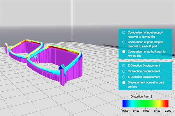
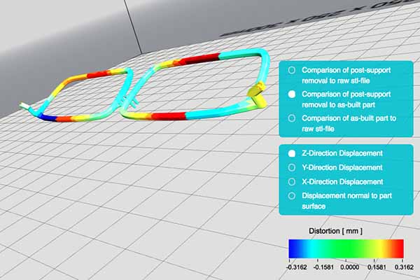
Supports also act as heat sinks during the build. Modelling software can help to predict which areas of the part are likely to experience high heat-induced stress and deformation, which can help the designer to modify their build program accordingly.
After removing the supports, some areas of this design will have localized stress zones not predicted in the initial CAD drawing.
Post-Finishing Should Not Be An Afterthought
Taking the above into consideration, it’s important to realize that every feature on your metal part is going to need some form of post-finishing. This could include sanding, grinding, filing, cutting or drilling. In plastic, this kind of finishing work can usually be done very simply by hand. In metal however the amount of extra time and effort is not trivial.

That’s why we recommend that designers carefully consider how they will finish their metal part after it’s printed. Whenever possible, save the complex geometries for internal areas or places without cosmetic importance. Exterior or appearance areas should be as smooth and featureless as practical for easier processing and the best results.
Engineering Advice For Your Metal 3D Printed Parts

In conclusion, here’s what to keep in mind when moving from traditional plastic printing solutions to metal powder bed fusion.
- Thermal heat management is the first priority
- Subtractive machining will also be needed once the metal part is printed
- Support placement goes hand-in-hand with thermal management and surface finishing
Metal 3D printing is a more complex process than it is for plastic printing, but for the most demanding applications the results are worth the extra effort.


