Injection Molded Reservoir for High-End Coffee Maker
Tool Making Process: CNC milling, CNC turning, EDM/wire EDM machining
Part Making Process: Plastic Injection Molding
Mold Material: NAK80 Steel
Part Materials: Eastman Tritan TX2001 Copolyester

About The Client
Marco Beverage Systems is a premium designer and manufacturer of specialty water boilers, filters, coffee makers and coffee grinders. Marco Beverage designs premium hot water dispensers, coffee brewing equipment and other accessories to high-end restaurants, corporate meeting rooms, private homes and other stylish venues.
About The Product
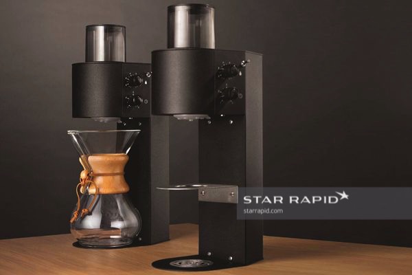
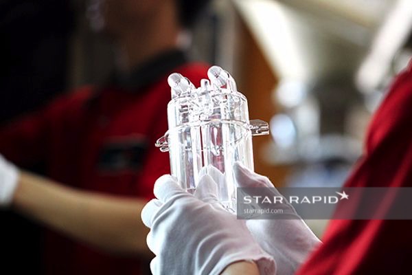
Marco Beverage needed a transparent and high-quality reservoir cup to supply hot water to their coffee making system. The reservoir is an integral part of the aesthetic, celebrating the experience of pour-over brewed coffee in high-exposure and fashionable locations.
About The Project
The team at Marco needed help in making a reservoir for an innovative new coffee brewing system. To ensure the team at Marco received the perfect parts, we had to meet the following design and engineering specifications:
– High-quality plastic
– Colorless, transparent
– Stable at high temperatures
– Resistant to cleaning products / dishwasher safe
– Compliant with safety regulations for food-grade plastics
– Strong and durable
– High-gloss surface finish
Design For Manufacturing Review
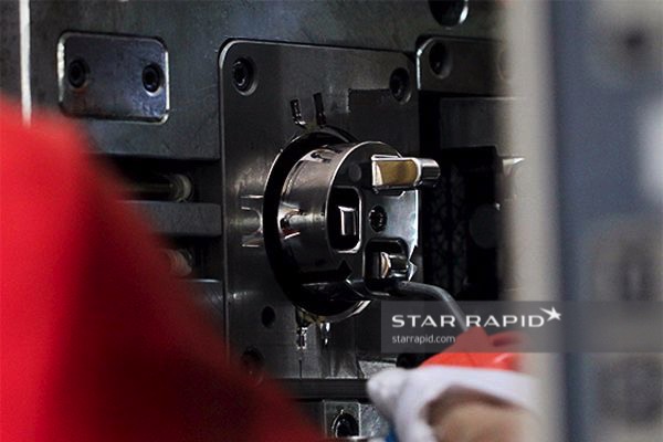
As with all of our projects, we began with a design review. Looking at the design showed us that this was a complex part with some really tricky challenges for the tool maker. For a plastic injection molding project like this, the main areas we were concerned about were the heating and cooling cycles, wall thickness, draft angles and support for the long, thin sections in the middle of the reservoir. As with any of our projects, our team worked closely with the client to explain and approve any suggested modifications.
Challenges
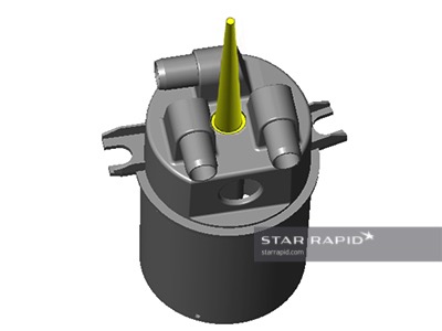
1. Injection Sprues
The yellow taper is just the sprue left over after injection. This needs to be broken off and trimmed flush with the base.
Challenge: The client was worried that breaking off this piece – especially when located in a hard-to-reach area – might actually rip a hole in the bottom of the cup. They wanted it to be reinforced on the other side with a dome of plastic.
Solution: We advised them to keep the base area flat. This is easier to mold and will look better. But in order to get a nice flush base, we agreed to cut off most of the sprue and then later machine it flat. More work, but a better finish.
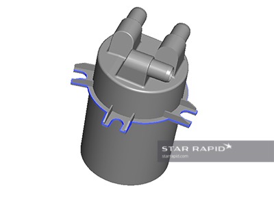
2. Draft Angles
The blue line shows where the cavity and core will separate – the parting line.
Challenge: As the core and cavity separate, this area will stick too much in the mold.
Solution: We put in a draft angle of 5°, enough to free the tool and still meet the functional and aesthetic requirements.
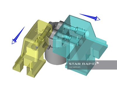
3. Thin Walls
There are three projecting inlet fittings at right angles to the opening direction of the mold tool.
Challenge: These features are thin-walled sections that need to be released separately from the main cavity/core.
Solution: Hydraulic sliding cores. Here you can see where the sliders will move aside in two different directions after injection. They create their own parting lines, but in this case these will be up against the base of the fittings and won’t create any cosmetic problems. There are also retractable pins inside of each core, which support the thin walls of the inlet and outlet fittings when the sliders are withdrawn. These can then be removed separately via spring action.
4. Long Projecting Columns
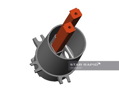
There are two long, thin-walled pipes inside of the cup reservoir for supplying the hot water.
Challenge: When the core and cavity are separated, these columns will be subject to strong elastic forces that would damage or destroy them.
Solution: We built additional hydraulic sliders into the core side, that were removed individually after the mold was fully open.
5. Manual Inserts
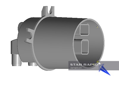
Three small holes needed to be molded into the cup around the circumference. These are intended for the later mounting of a locking cap.
Challenge: The mold is becoming complicated and expensive. How to mold these without additional hydraulic sliders?
Solution: This is an ideal place to use manual inserts which can easily be moved in and out by hand. It takes a little longer but greatly simplifies the tool making and keeps the cost down.
6. Cooling Channels
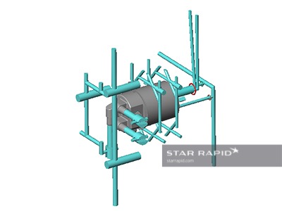
Cooling channels are essential for maintaining a uniform wall temperature during injection, which prevents warping.
Challenge: In this tool the channels are conventionally machined, which means they follow straight, line-of-sight paths. This is not ideal for following the curved contours of this shape.
Solution: We created multiple cooling channels in critical areas which is acceptable for a small prototype run. But here would be a perfect opportunity in future builds to take advantage of the conformal cooling channels made possible with metal 3D printing.
Choosing The Material
One of the most important decisions to make before manufacturing a product is to choose the right material for the job.
Challenge: Marco originally asked us to use Solvay Veradel A-301, which is a transparent food grade plastic. However, after we did some testing with the finished mold, we found that Solvay tends to degrade if it’s heated for too long. Since this project has a long injection cycle, it became too brittle in the thin-walled sections of the mold, making it unsuitable.
Solution: Our engineers found a substitute in Eastman Tritex 2001 copolyester. This plastic turned out to be stronger, more flexible and tolerant of the long heat cycle. Ideal for this application with a better result than the Solvay would have been. An unexpected surprise!
The Finished Product
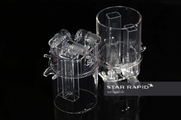
This build is a great example of how the close cooperation between a product developer and manufacturing engineers can help to overcome design challenges to ultimately create a beautiful product. We like these kinds of challenges and look forward to the next one!
Read about other great projects, or contact our team with your latest project design for a free quote and design for manufacturing review.
